Fiber-optic acoustic sensing

Fiber-optic microphones for measurement systems

A4 Sensors develops discrete fiber-acoustic sensing elements connected by a shared optical line. Sound pressure acts on a membrane, a measurement unit interrogates the line, and software extracts the signal from each microphone.

The development is intended for engineering acoustic measurements and operates as part of a fiber-optic system with centralized interrogation and signal processing.

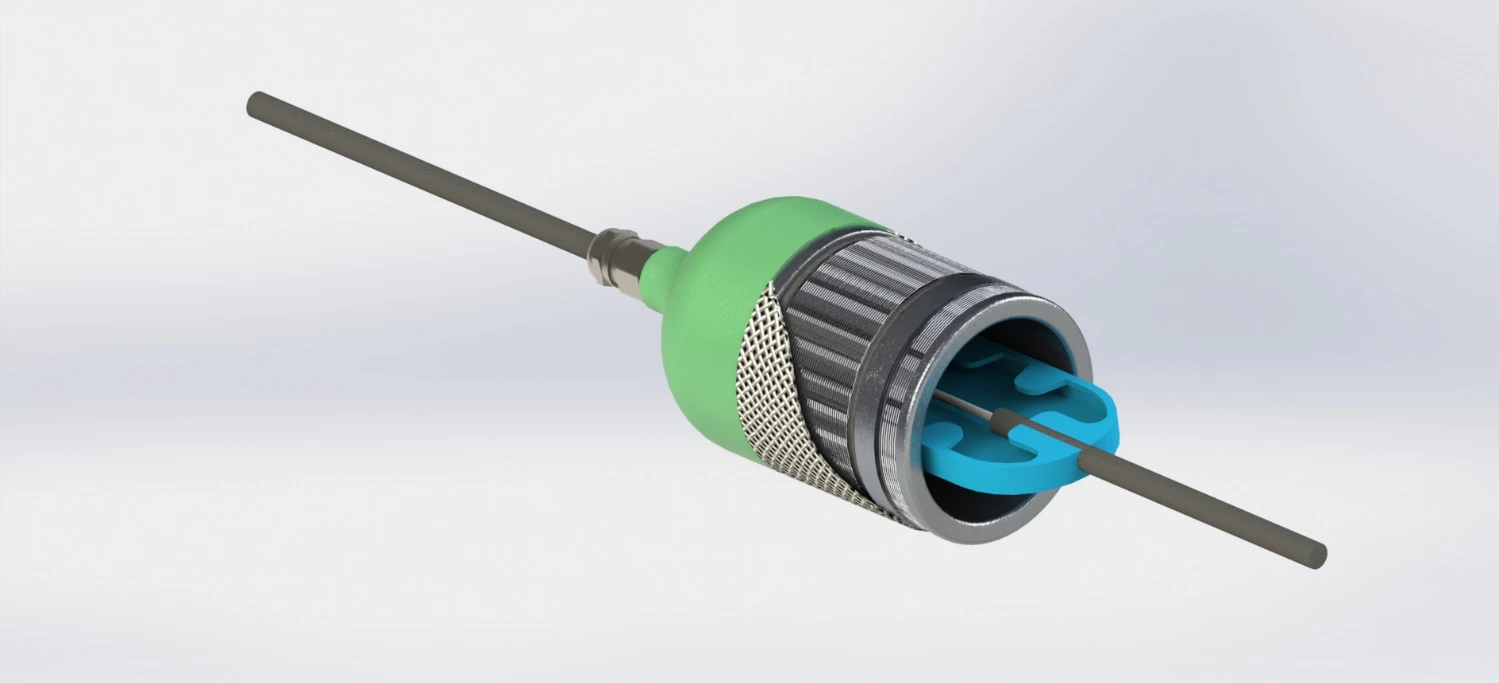
Construction of an A4Sensors fiber-optic microphone sensing element
Fiber-optic microphone / construction
  • Shared optical sensing line
  • No local power at each sensing element
  • Per-channel acoustic signal processing

Fiber-optic acoustics

A microphone as an optical sensing element

A fiber-optic microphone converts sound pressure on an acoustically sensitive membrane into a change in the optical signal. In the documented design, fiber is wound around the membrane, while weakly reflecting Bragg gratings separate measurement sections.

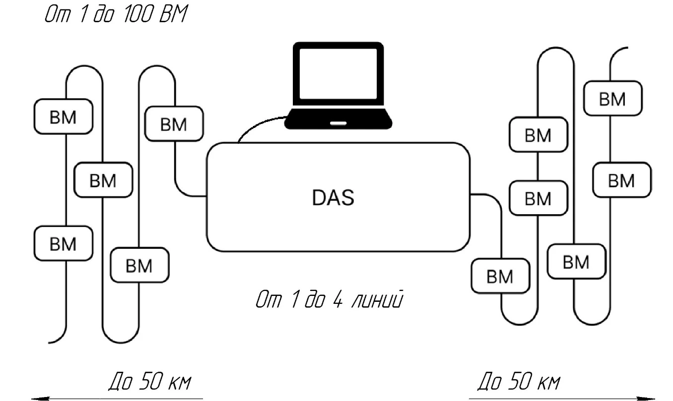
A sequence of elements connects to a shared fiber-optic line. A DAS unit interrogates it, and the software layer extracts each microphone's acoustic signal for per-channel and spectral processing.

  1. 01

    Sensing element

    Sound pressure acts on the membrane and changes the optical signal parameters in the measurement section.

  2. 02

    Shared interrogation line

    Multiple fiber-optic microphones connect through one optical line to the measurement unit.

  3. 03

    Centralized processing

    Software separates individual sensing channels and provides time-domain and spectral analysis.

Technology comparison

Optical and electrical approaches to sound measurement

The A4Sensors architecture is designed for engineering acoustic measurements: multiple fiber-optic sensing elements operate on a shared line with centralized interrogation and processing.

A4Sensors / measurement system

Fiber-optic microphone

The sensing element produces an optical response, operates on a shared line, and is interrogated by a specialized measurement unit.

  • Optical fiber and an acoustically sensitive membrane
  • Multiple elements on a shared sensing line
  • Per-channel and spectral processing in the software environment
Conventional audio systems

Electrical microphone

Converts sound into an electrical audio signal and operates as an individual channel for recording, communication, or sound reinforcement.

  • Electrical acoustic transducer
  • Individual wired or wireless audio channel
  • Recording, communication, and sound reinforcement

System architecture

From sound pressure to a separate acoustic channel

A shared optical line connects the sensing elements to the measurement unit and software.

  1. 01

    Acoustic event

    Sound pressure produces a mechanical response in the sensing-element membrane.

  2. 02

    Optical signal change

    The fiber structure converts membrane motion into a measurable change in optical response.

  3. 03

    Line interrogation

    A coherent DAS unit records the signal from measurement sections along the shared line.

  4. 04

    Per-channel processing

    Software extracts each microphone signal and performs time-domain and spectral analysis.

Experimental verification

From construction to a registered signal

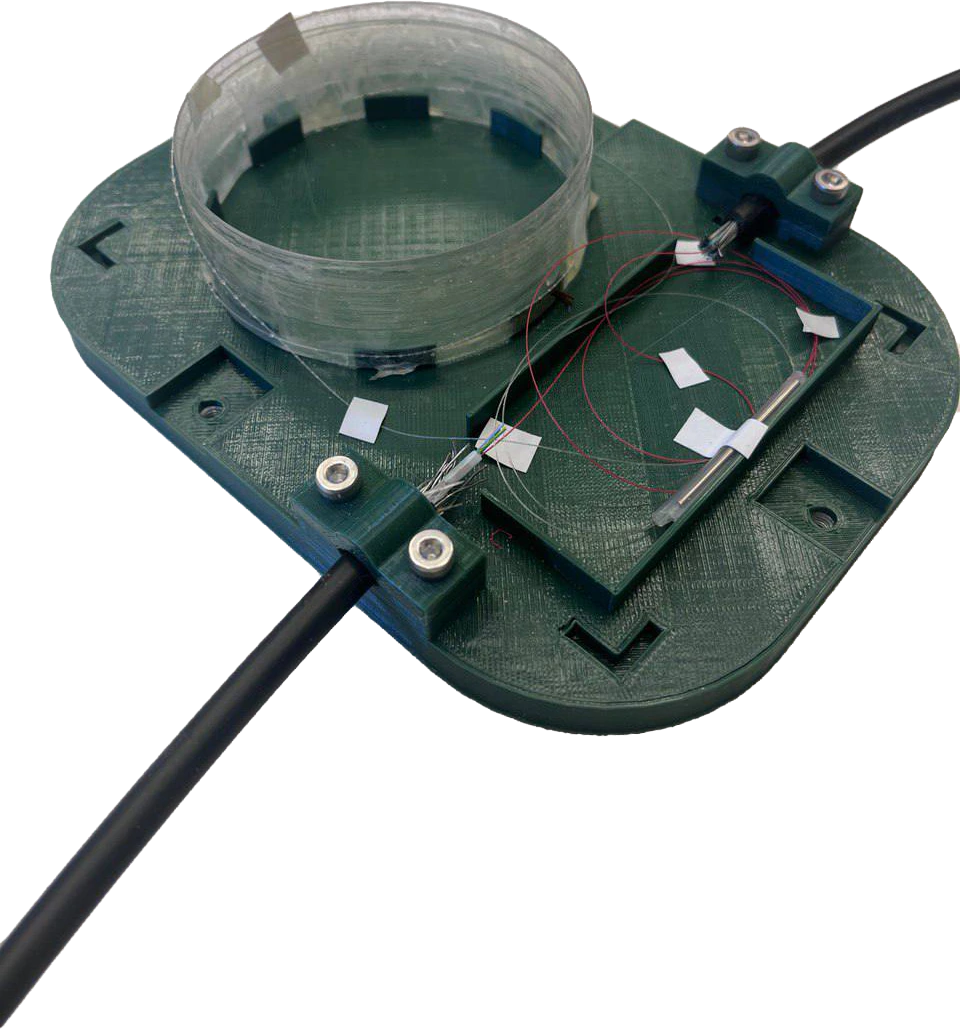
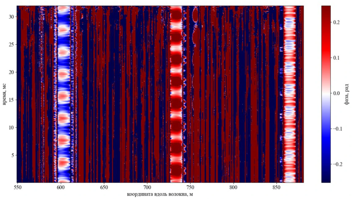
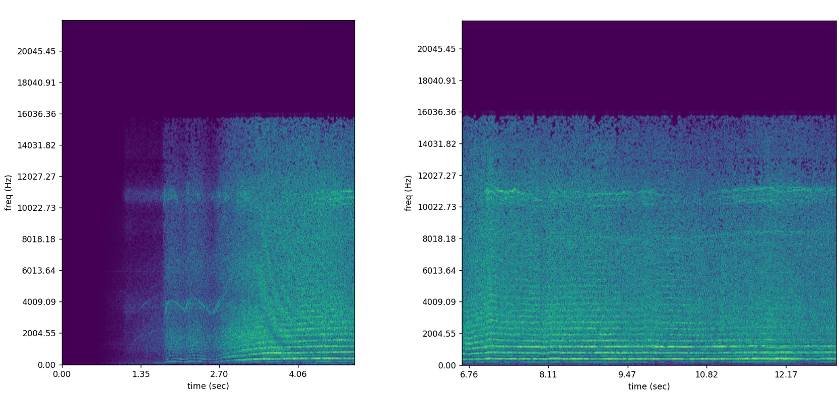
A4Sensors designed and assembled a fiber-optic microphone prototype. A three-microphone experiment produced a phase map and acoustic-signal spectrograms.

A4Sensors fiber-optic microphone prototype
Working prototype
Signal phase map from three fiber-optic microphones over time and position
Signal phase / time / position
Fiber-optic microphone acoustic signal spectrograms
Spectrum of the registered signal

Application directions

Multichannel acoustic measurement on a shared optical line

The current A4Sensors direction is in development and experimental verification. Its architecture is intended for tasks that need remote interrogation of multiple sensing elements and centralized processing.

01

Fiber-optic microphone array

Multiple discrete sensing elements form one line while their acoustic channels are extracted separately.

02

Equipment acoustic diagnostics

One civil application under consideration is recording and analyzing acoustic signals from industrial equipment.

03

Research measurements

The prototype and software environment support experiments with sensing-element geometry and processing algorithms.

Development in brief

Questions about fiber-optic microphones

01How is a fiber-optic microphone different from a conventional one?

A conventional microphone produces an electrical audio signal as a standalone device. In the A4Sensors development, sound changes an optical signal and the sensing element operates on a shared fiber-optic measurement line.

02Does each microphone need local power?

In the documented architecture, sensing elements connect to a shared optical line without local electrical power at every microphone.

03How are signals from multiple elements separated?

The measurement unit interrogates the line, while software extracts and processes the acoustic signal from each measurement section.

04What applications is the system intended for?

The development is intended for engineering acoustic measurements, experimental research, and systems with multiple sensing elements on a shared fiber-optic line.

Contact A4 Sensors

Let’s discuss your engineering challenge

Email usinfo@a4sensors.comCall us+7 906 727 3877